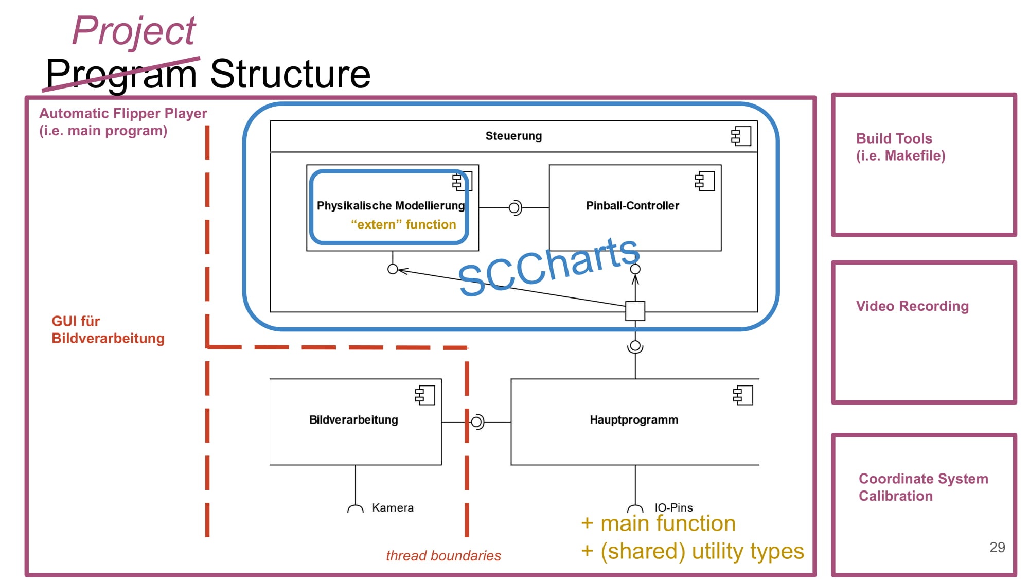
Slide 29 from the final presentation, the underlying component diagram is from planning/proposal; additional information in color presents more details of the actual final realization.
Blue boundaries are between C++ and SCCharts, red lines are thread boundaries, yellow additions are technical "components" that were not part of the original component diagram, purple shows other executables and build scripts.
The program is structured into multiple C++ source files and one SCChart. The main program (main.cpp) handles spawning threads and allocating reserved cores. There are multiple classes that hold global data for synchronization/communication between the threads, most of them defined in the image detection source file. (They act like channels, relying on locking or atomics depending on whether locking behavior could interrupt the SCChart or not.) These classes are instantiated in the main file in stack memory, each with one object, and for each thread that thread's main function is called with references to the communication objects that they need to access.
There are threads for
- Image detection (detection_main in detection.cpp)
- The SCChart and the loop around it managing the timed SCChart (timing_main in timing.cpp)
- The windows displaying the camera input and some details of the image detection (main loop of this thread is in main.cpp in wait_key_thread)
- When compiled not on the Raspberry Pi an additional thread handling the (keyboard controlled) timing / playback speed for the video file input (playback_controller in playback.cpp).
The main communication points between these threads are:
- The image detection sends ball positions and timestamps to the SCChart
- The image detection sends images to the thread handling the windows
- When compiled not on the Raspberry Pi the window threads sends keyboard input to the thread handling playback speed which in turn sends signals to image detection when to proceed to the next frame
The program generates debug outputs to the terminal from image detection and the SCChart about how much time processing each frame and executing each ticks takes.
There are some utility classes in seperate cpp files:
- In frame_timer.cpp a class that helps with generating stutter-free time-stamps for images going into the image detection.
- In position.cpp a data-type for specifying an x-y-coordinate (position) with some methods for common vector operations and interoperability with OpenCV datatypes.
- There's also a header file, magic.h, with some magic numbers as well as a bit of code for converting between different coordinate systems (pixel-coordinates in image vs. coordinates in meters relative to the lower center of the playing area).
- And there's a header calibration_config.h that can be regenerated by our calibration tool.
- Finally, physics.cpp contains functions for ball velocity calculation and path prediction that's used inside the SCChart.
- And there's a header file, stuff.h, that could be reincluded into the SCChart, defining some fine-tuned constants in a way that changing them doesn't require recompilation of the SCChart.
The SCChart is in sctx/controller.sctx, there are user-labels with a high-level description of (almost) every edge in the diagram. For an overview of the communication between all the regions, activate induced data-flow and compile the SCChart down to after Reference Expansion.

