Page History
| Panel | title | Project Overview
|---|
| Warning |
KIML has been discontinued and is replaced by the Eclipse Layout Kernel (ELK). |
| Panel | |||||
|---|---|---|---|---|---|
|
| ||||
Related Publications:
Related Theses:
|
Contents
| Table of Contents | ||
|---|---|---|
|
...
This subproject deals with the automatic layout of graph-based models. KIML offers interfaces to connect layout algorithms to diagram editors and viewers. The focus is on flexible configurability, which is a crucial issue for creating good layouts for different graphical languages and in different circumstances. The term meta layout relates to the idea of specifying the layout of a diagram on an abstract level, while concrete layout information is calculated by layout algorithms.
In order to use KIML with your own GMF-based editor, you need to do the following steps:
- Install the "KIELER Layout for GMF" feature from our update site, see Downloads
- It includes the Java-based layout algorithms developed in the KLay project.
- Open a diagram and press the layout button
 or use the shortcut Ctrl+R L.
Terminology
Layout Graph
- Internal representation of the graph structure of the current diagram, built on the KGraph model.
Layout Algorithm
- An algorithm that takes a layout graph as input and computes positions for all elements of the graph.
Layout Provider
- A component that provides one or more layout algorithms to KIML.
Layout Option
- A customization point for layout algorithms, with a specific data type and optionally a default value.
Layout Configurator
- A component that is responsible for retrieving specific layout option values for each model element.
Layout Data
- Concrete layout data (position and size) and abstract layout data (layout options) attached to elements of the layout graph using the KLayoutData model.
Layout Type
- Classification of layout algorithms depending on their basic approach (e.g. layered, force, etc.).
Diagram Type
- Classification of graphical diagrams used to set default layout option values for all diagrams of a specific type (e.g. state machines, data flow diagrams, etc.).
Diagram Layout Manager
- The central interface for connecting diagram editors with layout algorithms.
...
The main user interface element of KIML is the command to layout the current diagram. This command is availabe in the main KIELER menu, in the toolbar (), or using the Ctrl+R L shortcut. Additionally, an entry in the context menu allows to layout only a selected part of the diagram.
...
The Layout view allows flexible customization of layout options for the selected objects in the diagram. If no object is selected, the view shows the options for the top-level container of the diagram. Options are stored persistently in the notation model of the diagram, so that they are still available after the next Eclipse restart. Of course this requires the diagram to be saved after an option was changed.
The options are grouped according to the function of the selected objects. The group Nodes (respectively Edges, Ports, or Labels) contains options related to the object itself, such as its size or priority, while the group Parents contains options for the elements contained in the selected objects, such as the applied layout algorithm or the spacing between elements. Which layout options are displayed depends on the types of selected objects and the active layout algorithm, since each algorithm supports only a subset of the available options. Furthermore, some options are only visible if the Show Advanced Properties button in the view toolbar is activated. The group types can be hidden using the Show Categories button.
An option can be changed by selecting or entering a new value in the corresponding cell of the Value column. The most important option is Layout Algorithm, which is used to determine the layout algorithm for the contents of the selected element. Here either a specific layout algorithm or a layout type can be chosen; in the latter case, the most suitable layout algorithm of the given type is taken. By changing the active layout algorithm, the content of the layout view is updated to display only those options that are supported by the new layout algorithm.
Selecting Restore Default Value in the context menu or the view toolbar removes any value for the currently selected option that is stored in the current model file, thus resetting the option to its default value. The view menu has an entry Remove all Layout Options which resets all options of the current model by removing persistent data in the model file.
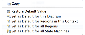
The context menu for a specific layout option has different alternatives to set the currently active value as default value: Set as Default for this Diagram changes the open model file so that the same value is applied to all similar objects of that model. Set as Default for ... in this Context applies the value to all similar objects that are displayed with the same diagram editor (the option is linked to the edit part class of the selected object). Choosing Set as Default for all ... links the option value with the domain model element or diagram type of the selected object (see the context menu depicted above). These four alternatives have different priorities: if present, the default value for the current diagram is taken first, then the default value for the edit part is checked, then the default value for the domain model element, and then the default value for the diagram type.
The information button of the view toolbar can be used to display some useful details on the current selection, such as the edit part and domain model classes.
...
If Set routing style of all edges to oblique is active, all routing styles and smoothness settings of edges are removed when automatic layout is performed. Since most layouters compute the routing of edges as part of their algorithm, these styles usually do not yield the expected results.
The Default Layout Option Values table is used to manage the default setting for layout options, which can also be modified with the context menu of the layout view (see above). All user-defined settings are displayed here, and the buttons on the right of the table serve to create, edit, and remove entries. The Type column shows the type of element the option is linked with: either edit part,model element, or diagram type. The Element column shows the class name for options that relate to edit parts or domain model elements, and the diagram type name for options that relate to diagram types. Option is the name of the layout option, and Value is the currently set value of the option.
Creating a new entry requires the selection of the type of related element and entering its class name or identifier. Class names of edit parts and domain model elements can be explored using the information button of the layout view, while diagram type identifiers can be selected with the Browse button. After that, a layout option has to be selected from the list using the corresponding Browse button. Hitting OK creates an entry, and its value can then be set using the Edit button.
Special Layout Options
While most layout options are used to affect how the active layout algorithm computes concrete coordinates for the graph elements, there are some layout options that have a special role in KIML.
Layout Algorithm
The option with identifier de.cau.cs.kieler.algorithm specifies which layout algorithm to use for the content of a composite node. The value can be either the identifier of a layout algorithm or the identifier of a layout type. In the latter case the algorithm with highest priority of that type is applied.
The following layout types are predefined:
- Layered - The layer-based method emphasizes the direction of edges by pointing as many edges as possible into the same direction. The nodes are arranged in layers and then reordered such that the number of edge crossings is minimized. Afterwards, concrete coordinates are computed for the nodes and edge bend points.
- Orthogonal - Orthogonal methods follow the "topology-shape-metrics" approach, which first applies a planarization technique, resulting in a planar representation of the graph, then compute an orthogonal shape, and finally determine concrete coordinates for nodes and edge bend points by applying a compaction method.
- Force - Layout algorithms that follow physical analogies by simulating a system of attractive and repulsive forces.
- Circular - Circular layout algorithms emphasize biconnected components of a graph by arranging them in circles. This is useful if a drawing is desired where such components are clearly grouped, or where cycles are shown as prominent properties of the graph.
- Tree - Specialized layout methods for trees, i.e. acyclic graphs. The regular structure of graphs that have no undirected cycles can be emphasized using an algorithm of this type.
Available Algorithms and Libraries
- The KLay Project - Java implementations of standard layout approaches, augmented with special processing of graph features such as ports and edge labels.
- Randomizer - Distributes the nodes randomly; not very useful, but it can show how important a good layout is for understanding a graph.
Box Layout - Ignores edges, places all nodes in rows. Can be used to layout collections of unconnected boxes, such as Statechart regions.
- Fixed Layout - Does not compute a new layout, but leaves all nodes and edges where they are. If the Position and Bend Points options are set for the elements of the graph, the pre-defined layout is applied.
- OGDF (www.ogdf.net) - A self-contained C++ class library for the automatic layout of diagrams. The version that is shipped with KIELER is compiled as an executable that reads files in OGML format and outputs the computed concrete layout.
- Graphviz (www.graphviz.org) - An open source graph visualization tool with several graph layout programs, web and interactive graphical interfaces, auxiliary tools, libraries, and language bindings. Graphviz needs to be installed separately in order to be used within KIELER, since it is called in a separate process using the DOT language for communication.
Diagram Type
Diagram types are used to classify graphical diagrams for setting default layout option values for a set of similar diagrams. The diagram type of an element is specified with the layout option de.cau.cs.kieler.diagramType. Layout algorithms can declare which diagram types they support well, and give a priority value for each supported type. KIML decides at runtime which layout algorithm has the highest priority for a given diagram, so that the most suitable algorithm is always used. Usual values for such priorities are between 1 and 10, where the highest value should only be assigned if the algorithm is especially designed for diagrams of the respective type, or if it has proven to be very adequate for them. Lower values should be given if the algorithm is able to draw the diagrams correctly, but with lower quality of the resulting layout.
The following diagram types are predefined:
- General - This type is automatically assigned to all diagrams for which no specific type is declared. A layout algorithm that has the highest priority on the General diagram type is taken as the default algorithm when no further information on a diagram is available to KIML.
- State Machine - All kinds of state machines, automata, and activity diagrams. Examples: SyncCharts, UML Activity diagrams.
- Data Flow Diagram - Actor-oriented diagrams, where connections are mostly done between ports of nodes. These diagrams can only be handled properly by very special layout algorithms, such as those developed in the KLay project.
- Class Diagram - Class diagrams such as Ecore diagrams for the EMF or UML Class diagrams.
- Use Case Diagram - Use case diagrams as defined by the UML.
- Unconnected Boxes - Sets of nodes that have no connections and are treated as resizable boxes. This is related to mathematical packing problems. Example: Regions in SyncCharts.
Other Options
- Layout Hierarchy (
de.cau.cs.kieler.layoutHierarchy) - If this option is supported and active, the layout algorithm is requested to process the full hierarchy contained in the input node. This means that instead of executing another algorithm on each hierarchy level, all levels are arranged in a single algorithm execution. - Hypernode (
de.cau.cs.kieler.hypernode) - A node that is marked as hypernode has a special role in the graph structure, since all its incident edges are treated as parts of the same hyperedge. Example: relation vertices in Ptolemy models. - Comment Box (
de.cau.cs.kieler.commentBox) - A node that is marked as comment box is treated as a label that needs to be placed somewhere. This is different to normal node labels, which are usually regarded as fixed. - No Layout (
de.cau.cs.kieler.noLayout) - Elements that are marked with this option are excluded from layout. This is used to identify diagram objects that should not be regarded as graph elements.
...
Related Theses:
|
Contents
| Table of Contents | ||
|---|---|---|
|
Getting Started
This subproject deals with the automatic layout of graph-based models. KIML offers interfaces to connect layout algorithms to diagram editors and viewers. The focus is on flexible configurability, which is a crucial issue for creating good layouts for different graphical languages and in different circumstances. The term meta layout relates to the idea of specifying the layout of a diagram on an abstract level, while concrete layout information is computed by layout algorithms.
In order to use KIML with your own GMF-based editor, you need to do the following steps:
- Install the "KIELER Layout for GMF" feature from our update site, see Downloads
- It includes the Java-based layout algorithms developed in the KLay project.
- Open a diagram and press the layout button or use the shortcut Ctrl+R L.
Similarly, the "KIELER Layout for Graphiti" feature provides the KIML interface to Graphiti-based editors.
Terminology
Layout Graph
- Internal representation of the graph structure of the current diagram, built on the KGraph model.
Layout Algorithm
- An algorithm that takes a layout graph as input and computes positions for all elements of the graph.
Layout Provider
- A component that provides one or more layout algorithms to KIML.
Layout Option
- A customization point for layout algorithms, with a specific data type and optionally a default value.
Layout Configurator
- A component that is responsible for retrieving specific layout option values for model elements.
Layout Data
- Concrete layout data (position and size) and abstract layout data (layout options) attached to elements of the layout graph using the KLayoutData model.
Layout Meta Data
- Meta information on layout algorithms, layout options, etc. gathered through extension points.
Meta Layout
- The process of creating abstract layout data (configuration of layout options) through layout configurators. In a more general sense, also used for the whole layout infrastructure.
Layout Type
- Classification of layout algorithms depending on their basic approach (e.g. layered, force, etc.).
Diagram Type
- Classification of graphical diagrams used to set default layout option values for all diagrams of a specific type (e.g. state machines, data flow diagrams, etc.).
Diagram Layout Manager
- The central interface for connecting diagram editors with layout algorithms.
Diagram Layout Engine
- A singleton class for invoking layout algorithms on diagram viewers and editors.
User Interface
The main user interface element of KIML is the command to layout the current diagram. This command is available in the toolbar () or using the Ctrl+R L shortcut. Additionally, an entry in the context menu allows to layout only a selected part of the diagram.
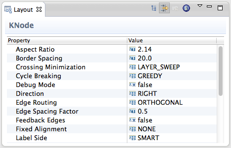
Layout View
The Layout view allows flexible customization of layout options for the selected objects in the diagram. If no object is selected, the view shows the options for the top-level container of the diagram. Options are stored persistently in the notation model of the diagram, so that they are still available after the next Eclipse restart. Of course this requires the diagram to be saved after an option was changed.
The options can be grouped according to the function of the selected object. The groups Node, Edge, Port, and Label contain options related to the object itself, such as its size or priority, while the groups Graph and Subgraph contain options for the elements contained in the selected object, such as the applied layout algorithm or the spacing between elements. Which layout options are displayed depends on the types of selected objects and the active layout algorithm, since each algorithm supports only a subset of the available options. Furthermore, some options are only visible if the Show Advanced Properties button in the view toolbar is activated. The group types can be hidden using the Show Categories button.
An option can be changed by selecting or entering a new value in the corresponding cell of the Value column. The most important option is Layout Algorithm, which is used to determine the layout algorithm for the contents of the selected element. Here either a specific layout algorithm or a layout type can be chosen; in the latter case, the most suitable layout algorithm of the given type is taken. By changing the active layout algorithm, the content of the layout view is updated to display only those options that are supported by the new layout algorithm.
Selecting Restore Default Value in the context menu or the view toolbar removes any value for the currently selected option that is stored in the current model file, thus resetting the option to its default value. The view menu has an entry Remove all Layout Options which resets all options of the current model by removing persistent data in the model file.
The standard layout options defined in KIML are documented in KIML Layout Options. However, layout algorithms may define additional layout options.
The context menu for a specific layout option has different alternatives to set the currently active value as default value: Set as Default for this Diagram changes the open model file so that the same value is applied to all similar objects of that model. Set as Default for ... in this Context applies the value to all similar objects that are displayed with the same diagram editor (the option is linked to the edit part class of the selected object). Choosing Set as Default for all ... links the option value with the domain model element or diagram type of the selected object (see the context menu depicted above). These four alternatives have different priorities: if present, the default value for the current diagram is taken first, then the default value for the edit part is checked, then the default value for the domain model element, and then the default value for the diagram type.
The information button of the view toolbar can be used to display some useful details on the current selection, such as the edit part and domain model classes.
Preference Page
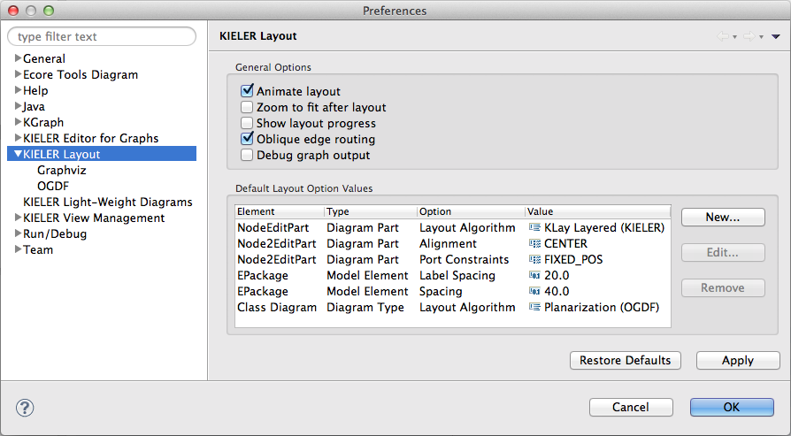
Animate layout enables animation of the transition of the old layout to the new layout whenever the layout is recomputed.
Automatic zooming can be enabled with Zoom to fit after layout.
If Show layout progress is active, a progress dialog is shown during the computation of layouts.
If Oblique edge routing is active, all routing styles and smoothness settings of edges are removed when automatic layout is performed on GMF editors. Since most layouters compute the routing of edges as part of their algorithm, these styles usually do not yield the expected results.
The option Debug graph output is used for debugging, as the name suggests. It writes the layout graph of each layout computation to a file in the current user's home directory.
The Default Layout Option Values table is used to manage the default setting for layout options, which can also be modified with the context menu of the layout view (see above). All user-defined settings are displayed here, and the buttons on the right of the table serve to create, edit, and remove entries. The Type column shows the type of element the option is linked with: either Diagram Part, Model Element, or Diagram Type. The Element column shows the class name for options that relate to diagram parts (i.e. edit parts) or domain model elements, and the diagram type name for options that relate to diagram types. Option is the name of the layout option, and Value is the currently set value of the option.
Creating a new entry requires the selection of the type of related element and entering its class name or identifier. Class names of diagram parts and domain model elements can be explored using the information button of the layout view, while diagram type identifiers can be selected with the Browse button. After that, a layout option has to be selected from the list using the corresponding Browse button. Hitting OK creates an entry, and its value can then be set using the Edit button.
Programming Interface
The primary API of KIML is the DiagramLayoutEngine, which is responsible for analyzing diagrams, creating a KGraph structure, configuring and executing the layout algorithms, and writing new position information back to the diagram.
...
The meta layout configuration is done by the LayoutOptionManager, which iterates over all graph elements and applies a set of layout configurators, represented by the interface ILayoutConfig. Layout configurators analyze the context of each graph element and set specific values for some layout options. Layout options are defined with the extension point layoutProviders. The most relevant layout configurators are listed in the following, with increasing priority.
...
It is invoked with
| Code Block | ||||
|---|---|---|---|---|
| ||||
DiagramLayoutEngine.INSTANCE.layout(workbenchPart, diagramPart) |
where workbenchPart is the Eclipse editor part or view part whose content shall be processed, and diagramPart is a further reference to which part of the diagram the layout shall be applied (may be null).
An overview of the internal structure of KIML is given in the following.
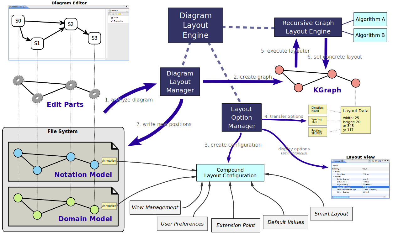
The interaction with the diagram editor or viewer is handled by layout managers, represented by IDiagramLayoutManager implementations, explained with more detail below.
The configuration of automatic layout is done by the LayoutOptionManager, which iterates over all graph elements and applies a set of layout configurators, represented by the interface ILayoutConfig. Layout configurators analyze the context of each graph element and set specific values for some layout options. More information on layout configuration is available on Configuring Automatic Layout.
Hierarchically structured graphs are handled by the RecursiveGraphLayoutEngine, which executes layout algorithms separately on each hierarchy level, starting with the innermost levels. The actual layout computations are performed by subclasses of AbstractLayoutProvider, which are registered with the layoutProviders
...
extension point.
The singleton class
...
LayoutMetaDataService is used to access the available layout algorithms, layout options, diagram types, layout types, and stored option values. Similarly, there are other service classes for accessing the meta data managed by KIML. Meta data are stored in XML format according to the extension points mechanism of Eclipse.
KIML makes extensive use of the IPropertyHolder interface; a property holder is an object that can give and receive values for specific properties. The key for specifying which property to access is IProperty, which is usually instanced exactly once for each property. The layout data classes KShapeLayout and KEdgeLayout are property holders, which means that they can store layout option values for the graph elements they are connected with.
Connecting Layout Algorithms
Layout algorithms must be connected by extending AbstractLayoutProvider. The input of the doLayout method is an instance of the KGraph, an EMF based graph structure, together with a progress monitor (IKielerProgressMonitor). The graph is represented by a KNode, which serves as top-level container. The contained graph elements initially have attached KShapeLayout or KEdgeLayout with information on the original layout of the diagram as well as an abstract layout specified by layout options. The layout provider should consider layout options from the attached layout data, execute a layout algorithm, and write the concrete results back to the layout data. A good example for a layout provider implementation is LayeredLayoutProvider.
The layoutProviders extension point is needed to register layout algorithms; one layout provider class may provide multiple layout algorithms by giving a parameter string in the extension point. The extension point allows to attach information on known layout options, supported
...
diagram types, and supported graph features to a layout algorithm. The known layout options are those that are offered in the Layout view when the respective algorithm is selected. The supported diagram types are used to automatically select the most suitable algorithm for a specific diagram type: from all algorithms that state to support a given type, the one with the highest priority is taken. The supported graph features are used to state which special features that a graph can contain can be handled by the algorithm; examples for such features are edge labels, ports, or clusters. Furthermore, the extension point can be used to specify new layout options, layout types, and categories of layout algorithms.
Each layout option that is registered in the extension point needs a corresponding constant in Java code, where the most relevant data is replicated with a Property constant for easy use in the implementation of layout algorithms. KIML comes with a large set of built-in layout options, which are all defined in LayoutOptions. Layout providers can access the layout option values using the IPropertyHolder interface:
| Code Block | ||||
|---|---|---|---|---|
|
...
KShapeLayout nodeLayout = parentNode.getData(KShapeLayout.class);
boolean isInteractive = nodeLayout.getProperty(LayoutOptions.INTERACTIVE); |
The layout option that is used in this example has a default value, thus it is guaranteed that the option always returns a valid value. This and the fact that properties are type-safe allows us to implicitly cast and unbox the returned value to a boolean without checking for NullPointerExceptions or ClassCastExceptions.
Connecting Diagram Editors
The
...
The transformation of input diagrams to KGraph instances as well as the transfer of computed layouts back to the input diagrams is done by IDiagramLayoutManager implementations. For most diagram editors that are based on GMF the generic GmfDiagramLayoutManager can be used, while for Graphiti there is the generic GraphitiDiagramLayoutManager. However, some customized diagram editors do not work with the generic diagram layout managers and hence require their own specialized implementations, which can be contributed with the extension point layoutManagers.
...
transformation of input diagrams to KGraph instances as well as the transfer of computed layouts back to the input diagrams is done by IDiagramLayoutManager implementations. For most diagram editors that are based on GMF the generic GmfDiagramLayoutManager can be used, while for Graphiti there is the generic GraphitiDiagramLayoutManager. However, some customized diagram editors do not work with the generic diagram layout managers and hence require their own specialized implementations, which can be contributed with the extension point layoutManagers.
The diagram layout manager implementation that is applicable to the currently selected diagram viewer is chosen based on the supports(Object) method: the first implementation that returns true for the respective workbench part instance is selected. Implementations can be assigned a priority in the extension; diagram layout managers with higher priority are queried first. The object passed to supports(Object) can also be an element of the selection. For example, GEF-based editors report edit part instances to the Eclipse selection service. Which diagram layout manager to use for a selected edit part is determined by testing which implementation supports that edit part instance.
Each diagram layout manager must be able to map the graph structure of its supported diagram viewers to the KGraph format using the buildLayoutGraph(…) method. The result is stored in a LayoutMapping, which stores a bidirectional map between graph elements and diagram elements and can be enriched with additional information. Such information is often required when the new computed layout is applied back to the diagram, which is done with applyLayout(…). This method is also responsible for applying animation of the transition between the old layout and the new layout and for automatic zooming, if requested.
There are many ways to customize the configuration of graphs created by layout managers. These are documented in Configuring Automatic Layout.
Overview
Content Tools