Page History
...
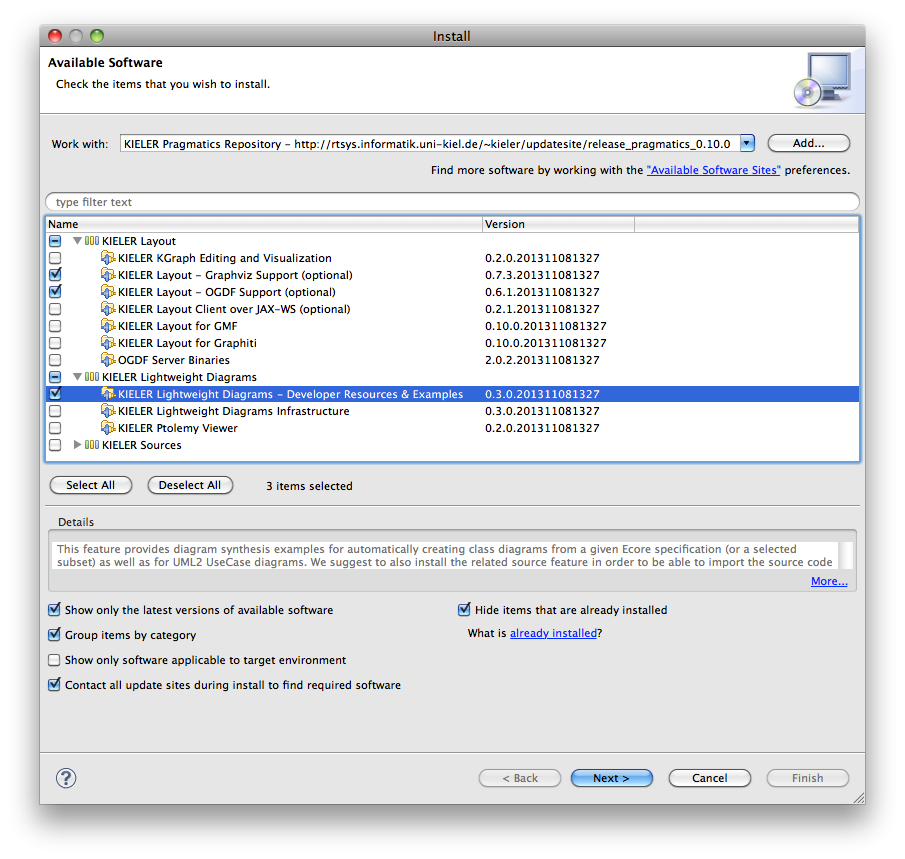
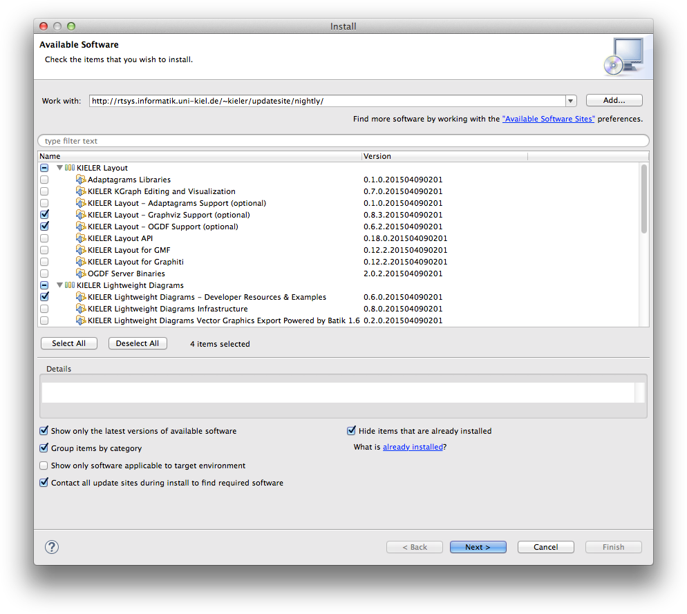
In order to build up your own diagrams by means of KLighD we suggest to install some of our provided features from our update site http://rtsys.informatik.uni-kiel.de/~kieler/updatesite/release_pragmatics_0.10.0: (If you seek for diagrams with nodes and edges connected via ports (as depicted in Figure 2 in Just Model! - ...), there's a new example illustrating this that is not part of our latest release. Hence, refer to the latest nightly build, or checkout our source code (get the repository url via 'Clone' in the upper right corner)):
- KIELER Lightweight Diagrams – Developer Resources & Examples:
This feature includes KLighD's & KIML's runtime as well as a few developer tools (e.g. a convenient project wizard) and a few prepared example diagram synthesis implementations. Besides, all source bundles will be installed.
Note: KIELER Lightweight Diagrams Demo Examples is part of an older release as indicated by the timestamp in the version number. It is superseded by Developer Resources & Examples. - KIELER Layout – Graphviz support (optional):
This feature enables the employment of Graphviz' layouters,dotis very popular for simple graphs with edge labels. Note that employing Graphviz requires to also install the native library, see http://www.graphviz.org/ - KIELER Layout – OGDF support (optional):
This feature enables the employment of OGDF' layouters, itsplanarizationis the recommended algorithm for arranging UML Class Diagrams. The required OGDF Server Binaries will be automatically installed, too!
Create first diagrams
...
Create a KNode (via createNode()) for each element comprised by the given instance model (usually called the business, domain, or semantic model) of your data type, here EPackage. Add those nodes to the children of root. Create a KEdge for each relation or link to be contained in your diagram. Similarly to createNode() there is createEdge() for that purpose. Set source and target node of those edges accordingly, this will implicitly add the edges to the diagram (via EMF's EOpposite mechanism). You can reveal an already created node representing a certain domain element by calling domainElement.getNode(), or simply domainElement.node. Have a look at UML2UseCaseDiagramSynthesis, which is part of our examples project, on how to do that. If you interested in diagrams with nodes and edges connected via ports (as depicted in Figure 2 in Just Model! - ...) have a look at CircuitDiagramSynthesis. Note that this example is not part of our latest release yet so install a nightly build (sorry for its bugs ![]() ) or checkout our source code (get the repository url via 'Clone' in the upper right corner).
) or checkout our source code (get the repository url via 'Clone' in the upper right corner).
Finally attach figure specifications to the nodes and edges, most conveniently by means of the extension methods provided by the ...Extension classes - see the use case example on that, too. A documentation of those methods in form of a list of all extension methods sorted by the type they can be used with can be found here. (And yes, there is still some lack of documentation...)
...
Overview
Content Tools