KLighD has been moved to GitHub.
Project Overview
Related Publications:
- Christian Schneider, Miro Spönemann, and Reinhard von Hanxleden. Just Model! – Putting Automatic Synthesis of Node-Link-Diagrams into Practice. In Proceedings of the IEEE Symposium on Visual Languages and Human-Centric Computing (VL/HCC’13), San Jose, CA, USA, 15–19 September 2013. Original publication is available via IEEE Xplore® (pdf / bib / poster).
Christian Schneider, Miro Spönemann, and Reinhard von Hanxleden. Transient view generation in Eclipse. In Proceedings of the First Workshop on Academics Modeling with Eclipse (AcME), Kgs. Lyngby, Denmark, 2012. Original publication is available in the joint proceedings of the co-located events on the website of the 8th European Conference on Modelling Foundations and Applications (ECMFA'12) (pdf / bib).
Get the demo example DSL and KLighD diagram synthesis shown at XtextCon 2015 as well as the test model from here!
This page has been updated to KIELER Pragmatics 0.11.0
Contents
The Big Picture
The KIELER Lightweight Diagrams (KLighD) project aims at offering transient lightweight representations of models or parts of them, without incorporating complex editing facilities like graphical editors.
Instead graphical or textual representations are to be synthesized from a chosen fraction of a model base and dismissed if they are not needed anymore. This way the Model-View-Controller paradigm (MVC) shall be established at the users' front end of modeling tools. Although KLighD is intended to address graphical as well as textual transient views, the graphical ones are currently in the focus. The automatic arrangement of those views (macro layout) is contributed by KIML.
Feel free to watch the following videos illustrating the idea and possibilities of transient views of models:
- http://rtsys.informatik.uni-kiel.de/~kieler/videos/klighd/InstantModelBrowsingAnnotated.mp4
- http://rtsys.informatik.uni-kiel.de/~kieler/videos/klighd/TextualModeling.mp4
- http://rtsys.informatik.uni-kiel.de/~kieler/videos/klighd/SCT.mp4 (textual modeling continued)
- http://rtsys.informatik.uni-kiel.de/~kieler/videos/klighd/SCG.mp4
- http://rtsys.informatik.uni-kiel.de/~kieler/videos/ptolemyViewer/PtolemyViewerHQ.mp4
For details on the objectives of our KLighD framework have a look at the above mentioned publication Just Model! – Putting Automatic Synthesis of Node-Link-Diagrams into Practice (Sec. I, III, & V) first.
Getting Started
Installation
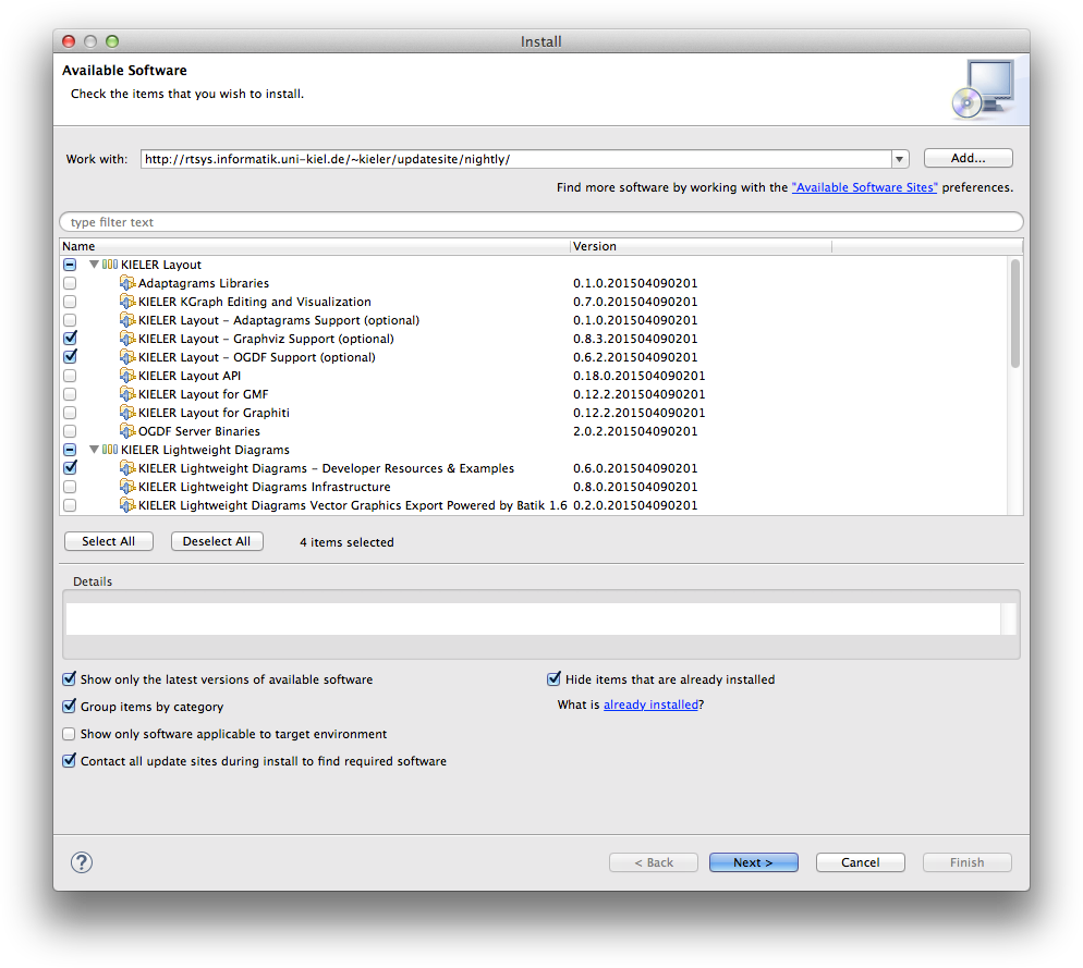
In order to build up your own diagrams by means of KLighD we suggest to install some of our provided features from our update site http://rtsys.informatik.uni-kiel.de/~kieler/updatesite/:
- KIELER Lightweight Diagrams – Developer Resources & Examples:
This feature includes KLighD's & KIML's runtime as well as a few developer tools (e.g. a convenient project wizard) and a few prepared example diagram synthesis implementations. Besides, all source bundles will be installed.
Note: KIELER Lightweight Diagrams Demo Examples is part of an older release as indicated by the timestamp in the version number. It is superseded by Developer Resources & Examples. - KIELER Layout – Graphviz support (optional):
This feature enables the employment of Graphviz' layouters,dotis very popular for simple graphs with edge labels. Note that employing Graphviz requires to also install the native library, see http://www.graphviz.org/ - KIELER Layout – OGDF support (optional):
This feature enables the employment of OGDF' layouters, itsplanarizationis the recommended algorithm for arranging UML Class Diagrams. The required OGDF Server Binaries will be automatically installed, too!
Create first diagrams
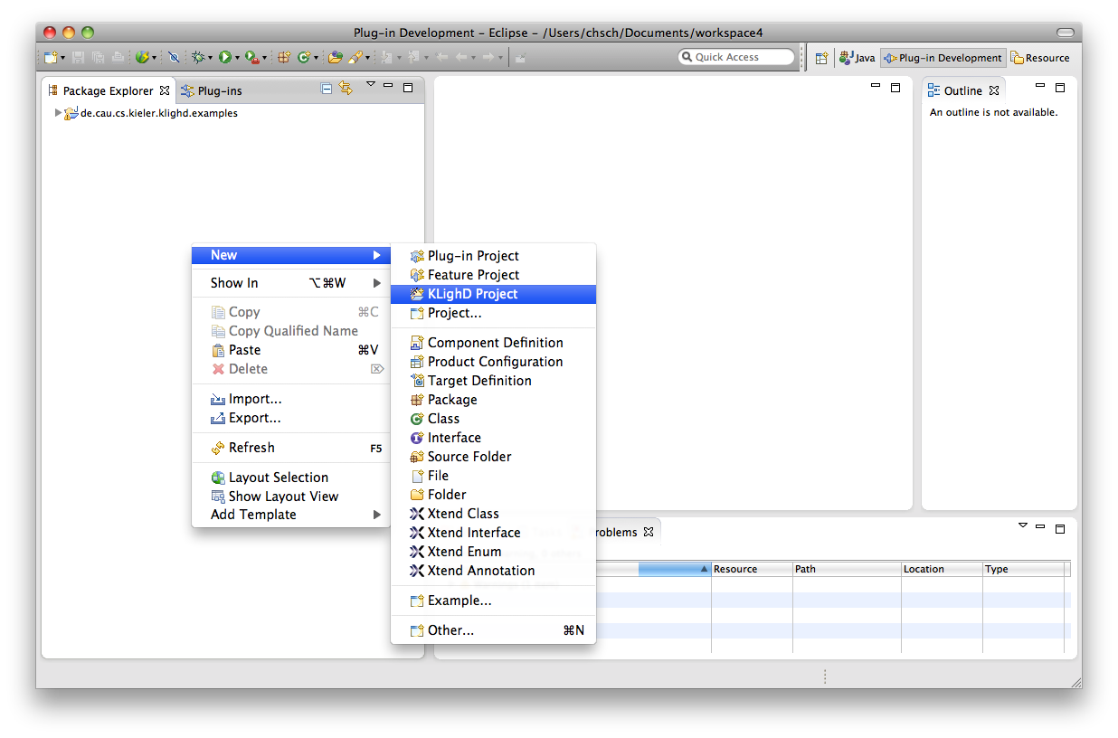
In order to let the framework draw your desired diagrams for representing given data we need to tell KLighD how to obtain nodes, edges, and hierarchy levels from the provided data. To this end we need to implement a so called diagram synthesis. Getting an initial stub of such an implementation is most easiest done by means of our KLighD project wizard (if the entry is not visible, switch the perspective or close and reopen it, or simply choose Other... → KIELER Light-weight diagrams):
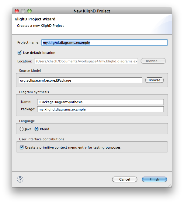
Provide the source model type, e.g. via the 'Browse' button. Note that the project containing that class must exist in the workspace or at least any other workspace project must have this class in its class path, e.g. via a bundle dependency. Otherwise it won't be offered by the list of available classes. Of course you might alter the project's name, the name of the diagram synthesis implementation and its containing package. Finally choose your favorite implementation language - we like Xtend very much for this purpose! ![]() If you don't like to have a simple popup menu contribution for testing purposes, uncheck the corresponding checkbox.
If you don't like to have a simple popup menu contribution for testing purposes, uncheck the corresponding checkbox.
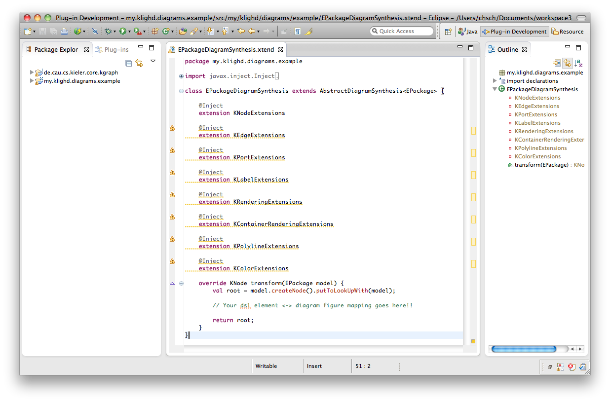
You will get the following implementation template, it is already registered via KLighD's dedicated extension point (see the project's plugin.xml).
Before starting with the implementation let us point you at some hints on using Xtend!
Create a KNode (via createNode()) for each element comprised by the given instance model (usually called the business, domain, or semantic model) of your data type, here EPackage. Add those nodes to the children of root. Create a KEdge for each relation or link to be contained in your diagram. Similarly to createNode() there is createEdge() for that purpose. Set source and target node of those edges accordingly, this will implicitly add the edges to the diagram (via EMF's EOpposite mechanism). You can reveal an already created node representing a certain domain element by calling domainElement.getNode(), or simply domainElement.node. Have a look at UML2UseCaseDiagramSynthesis, which is part of our examples project, on how to do that. If you are interested in diagrams with nodes and edges connected via ports (as depicted in Figure 2 in Just Model! - ...) have a look at CircuitDiagramSynthesis. For convenience you might also want to import the examples project into your workspace. Simply switch to the Plug-ins view and import de.cau.cs.kieler.klighd.examples as Source Project, see screen shot below.
Finally attach figure specifications to the nodes and edges, most conveniently by means of the extension methods provided by the ...Extension classes - see the use case example on that, too. A documentation of those methods in form of a list of all extension methods sorted by the type they can be used with can be found here. (And yes, there is still some lack of documentation...)

Invoking the diagram synthesis
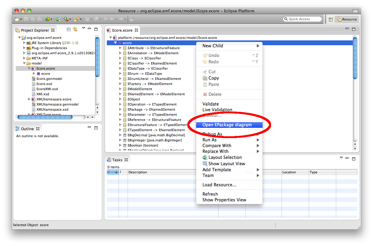
Testing the diagram synthesis is most easiest done by means of the test menu contribution created by the project wizard. Thus, start a test Eclipse Application via 'Run As', e.g. via 'Run' in the main menu. Import or create a project with some of your model data. If your model format has been described by means of Ecore, you can open your model with a matching EMF tree editor as shown in the following screenshot (here we used the Ecore format itself, so we used an "arbitrary" Ecore model ![]() ).
).
Open the context menu while an instance of your source model type is selected, and hit the Open ... diagram entry. Btw.: The menu entry is enabled as far as the selected elements are of your source model type. Hence, there may be other ways (views or editors) to open the diagram beyond those EMF tree editors.
Alternatively, you might want to create your own menu contribution. Here are some instructions using the Eclipse 3.X API: Register a command with some arbitrary id and a default handler. In the execute() method of your handler call
DiagramViewManager.getInstance().createView(<<someId>>, <<someName>>, <<yourConcreteData>>, KlighdSynthesisProperties.emptyConfig());
This statements will open an eclipse view part showing your desired diagram. <<someId>> is an the Id that can be used to access, update, or close the view part later on programmatically, and <<someName>> is the name of the view (shown at the view's tab), <<yourConcreteData>> is an instance of the input type of your diagram synthesis implementation. Via the last parameter some additional instructions can be handed over. For those that are not yet familiar with Eclipse menu stuff have a look on at a corresponding tutorial, e.g. at vogella.com.
Exemplary diagram syntheses
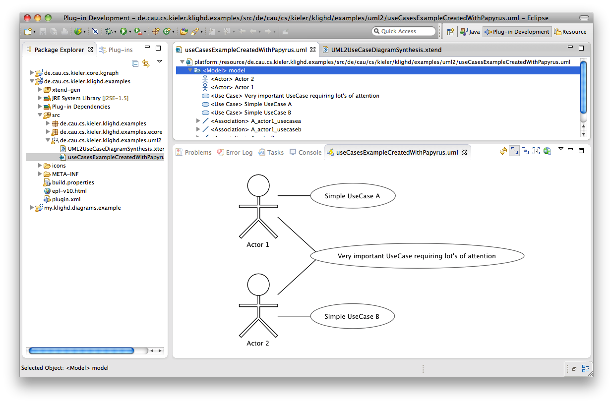
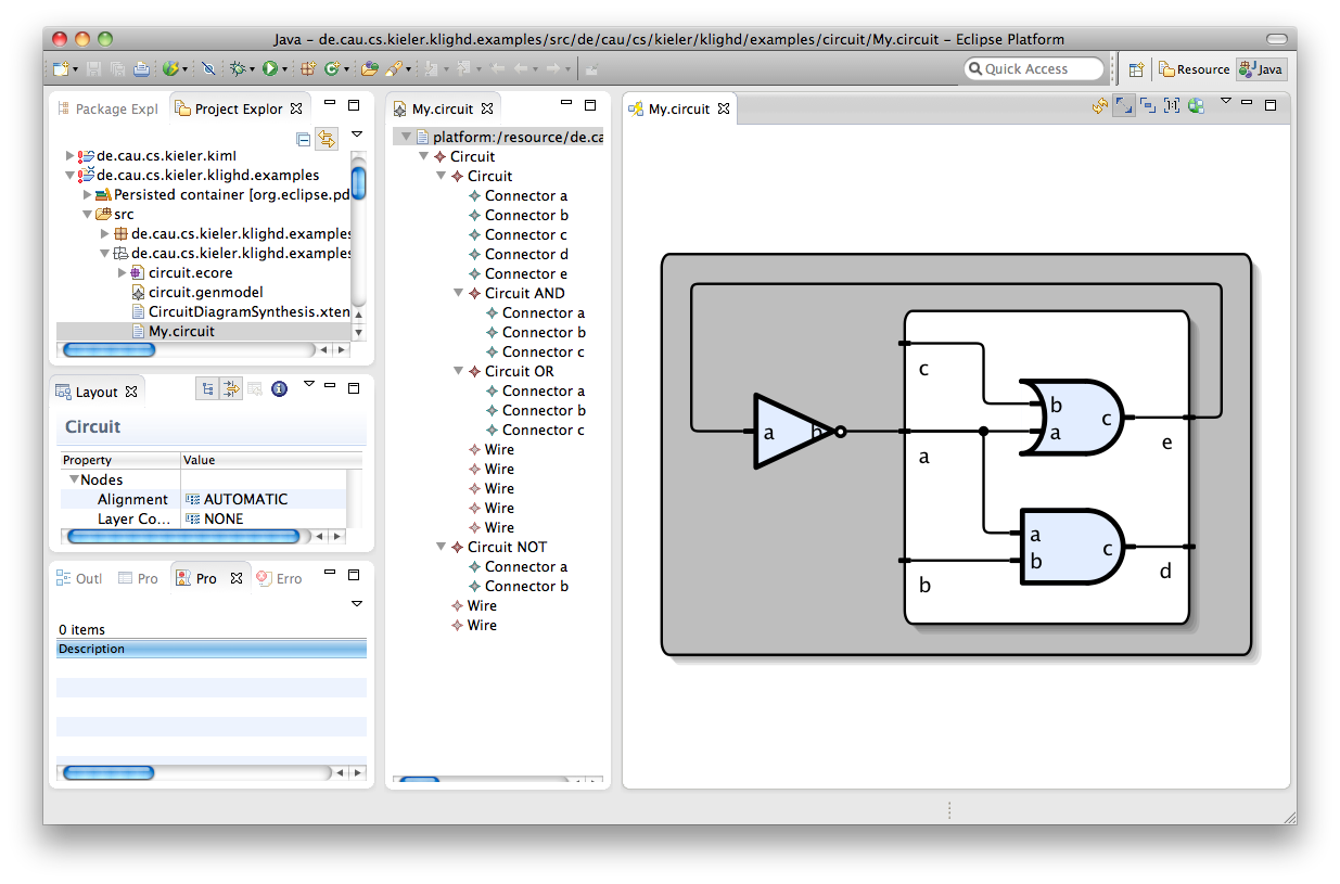
Exemplary use case diagrams (created by the UML2UseCaseDiagramSynthesis) and circuit diagrams (created by the CircuitDiagramSynthesis) are shown in following screenshots, the source UML & Circuit models are part of the examples project, too. In order to obtain those diagrams enable the automatic diagram creation by activating Visualize EMF tree editor content (KLighD) as shown below.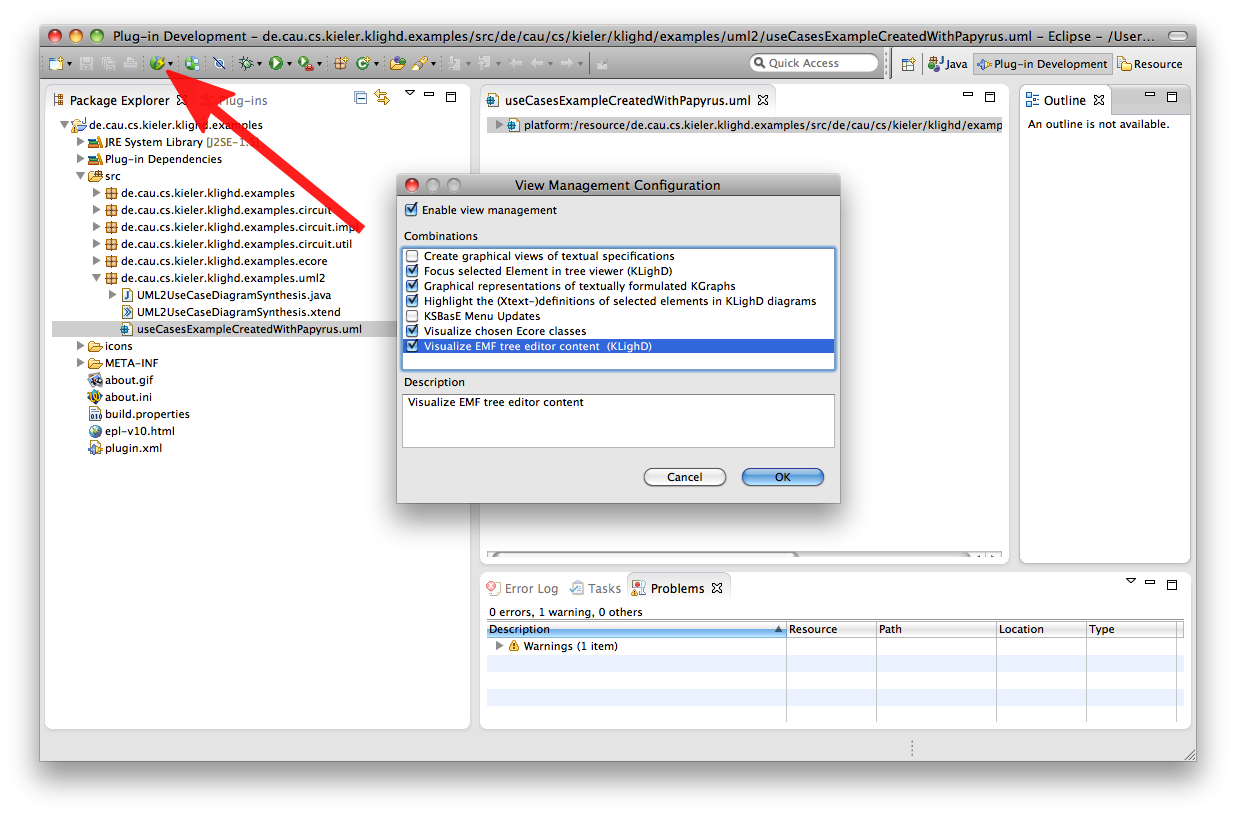
Then open the models and select one of its elements (open My.circuit with the Sample Reflective Ecore Model Editor).
Advanced diagram synthesis features
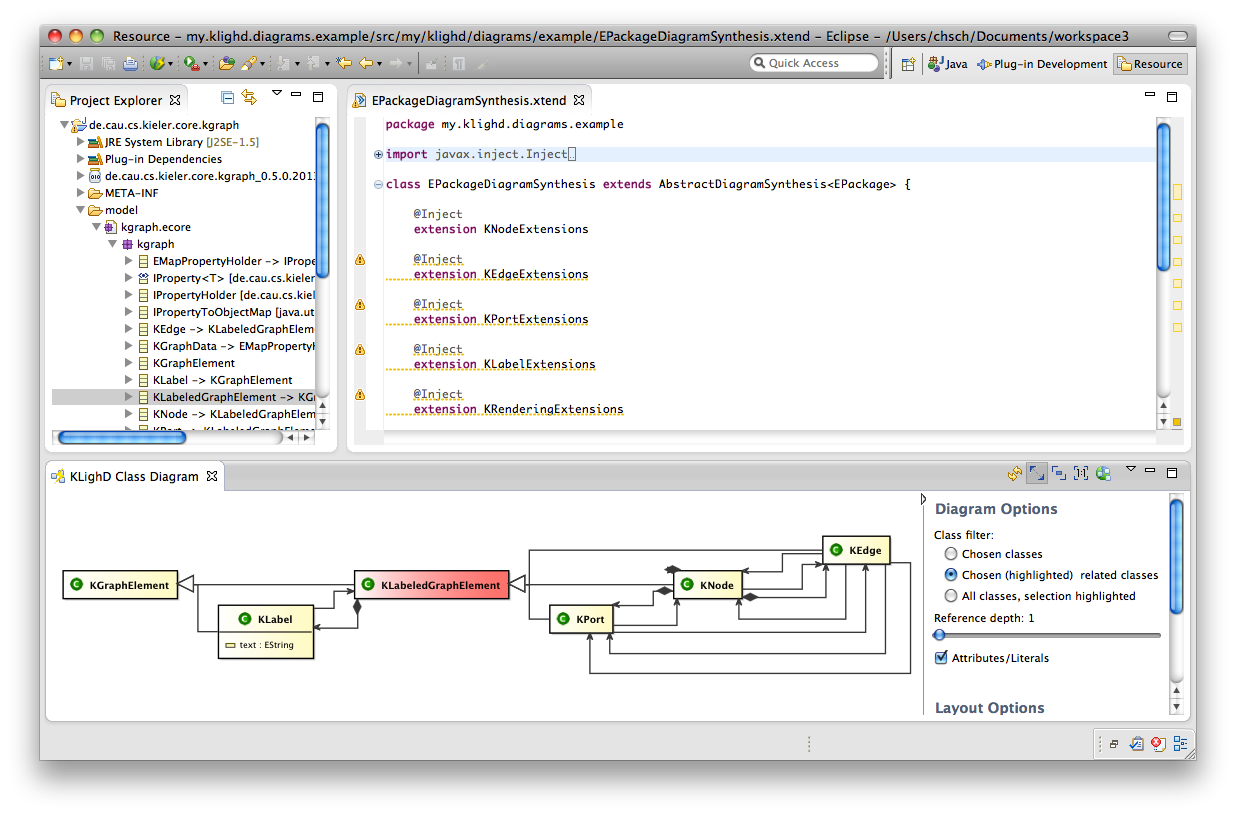
Now you might want to use some advanced features of KLighD diagrams, like sophisticated figure styling or diagram synthesis options. Details on that will follow soon, the EcoreDiagramSynthesis, which is in charge of creating appealing class diagrams from Ecore models and which you will also find in the examples project, illustrates those features already. The following picture shows such a diagram and a list of options for tailoring such diagrams in the side bar on the right.
Trouble shooting
- Be sure to compile your Eclipse plug-in project with Java 5 or Java 6 compatibility.
- Increase the
perm memorysize with the VM argument-XX:MaxPermSize=128M(Arguments tab of your Eclipse run configuration) if you get aPermGen spaceexception.
Incorporated Technologies
Overview
Content Tools