KIML defines a whole set of standard layout options that many layout algorithms support. When an option is supported by an algorithm, that algorithm may override the option's default value. Algorithms may also provide more specialized documentation for layout options.
Contents
Overview
Beside a user-friendly name, layout options are defined by the following properties:
- An ID to identify them.
- A type. One of Boolean, String, Int, Float, Enum, EnumSet (a s
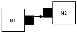
etover a given enumeration), or Object (a non-primitive Java object). The types Enum and EnumSet have to be further defined by an enumeration class. The Object type can be constricted to a certain Java class. - The kinds of graph objects the option applies to. At least one of Nodes, Edges, Ports, Labels, or Parents (nodes that have children, including the diagram root node). Parents-applicable options affect whole graphs or subgraphs, while options with other application targets affect only single graph elements.
- An optional default value. A default value may also be provided by the layout algorithm using the option, or by the modeling application you are using. In these cases the value given here is overridden.
Layout options can be assigned to two main categories: user options and programmatic options.
User Options
User options are those that you can see in the "Layout View" available in Eclipse if the KIML user interface is installed. That view is restricted to layout options that are supported by the currently active layout algorithm. Furthermore, some options are visible only when the Show Advanced Properties button is active in the view.
| Option | ID | Type | Applies to | Default |
|---|---|---|---|---|
| Alignment | de.cau.cs.kieler.alignment | Enum | Nodes | AUTOMATIC |
| Aspect Ratio | de.cau.cs.kieler.aspectRatio | Float | Parents | 0.0 |
| Bend Points | de.cau.cs.kieler.bendPoints | Object | Edges | |
| Border Spacing | de.cau.cs.kieler.borderSpacing | Float | Parents | |
| Debug Mode | de.cau.cs.kieler.debugMode | Boolean | Parents | false |
| Direction | de.cau.cs.kieler.direction | Enum | Parents | |
| Edge Routing | de.cau.cs.kieler.edgeRouting | Enum | Parents | |
| Expand Nodes | de.cau.cs.kieler.expandNodes | Boolean | Parents | false |
| Interactive | de.cau.cs.kieler.interactive | Boolean | Parents | false |
| Label Spacing | de.cau.cs.kieler.labelSpacing | Float | Edges Nodes | |
| Layout Hierarchy | de.cau.cs.kieler.layoutHierarchy | Boolean | Parents | false |
| Layout Algorithm | de.cau.cs.kieler.algorithm | String | Parents | |
| Node Label Placement | de.cau.cs.kieler.nodeLabelPlacement | EnumSet | Nodes Labels | |
| Port Constraints | de.cau.cs.kieler.portConstraints | Enum | Nodes | |
| Port Label Placement | de.cau.cs.kieler.portLabelPlacement | Enum | Nodes | OUTSIDE |
| Port Spacing | de.cau.cs.kieler.portSpacing | Float | Nodes | |
| Port Alignment | de.cau.cs.kieler.portAlignment | Enum | Nodes | JUSTIFIED |
| Port Alignment for Northern Ports | de.cau.cs.kieler.portAlignment.north | Enum | Nodes | UNDEFINED |
| Port Alignment for Souther Ports | de.cau.cs.kieler.portAlignment.south | Enum | Nodes Parents | UNDEFINED |
| Port Alignment for Eastern Ports | de.cau.cs.kieler.portAlignment.east | Enum | Nodes Parents | UNDEFINED |
| Port Alignment for Western Ports | de.cau.cs.kieler.portAlignment.west | Enum | Nodes Parents | UNDEFINED |
| Position | de.cau.cs.kieler.position | Object | Labels | |
| Priority | de.cau.cs.kieler.priority | Int | Edges Nodes | |
| Randomization Seed | de.cau.cs.kieler.randomSeed | Int | Parents | |
| Separate Connected Components | de.cau.cs.kieler.separateConnComp | Boolean | Parents | |
| Size Constraint | de.cau.cs.kieler.sizeConstraint | EnumSet | Nodes | |
| Size Options | de.cau.cs.kieler.sizeOptions | EnumSet | Nodes | DEFAULT_MINIMUM_SIZE |
| Spacing | de.cau.cs.kieler.spacing | Float | Parents |
Programmatic Options
Programmatic options are such that are meant to be configured exclusively through the KIML API. They should not be visible in the user interface.
| Option | ID | Type | Applies to | Default |
|---|---|---|---|---|
| Additional Port Space | de.cau.cs.kieler.additionalPortSpace | Margins | Nodes | 0, 0, 0, 0 |
Animate | de.cau.cs.kieler.animate | Boolean | Parents | true |
Animation Time Factor | de.cau.cs.kieler.animTimeFactor | Int | Parents | 100 |
de.cau.cs.kieler.commentBox | Boolean | Nodes | false | |
| Diagram Type | de.cau.cs.kieler.diagramType | String | Parents | |
| Edge Label Placement | de.cau.cs.kieler.edgeLabelPlacement | Enum | Labels | |
| Edge Type | de.cau.cs.kieler.edgeType | Enum | Edges | NONE |
| Font Name | de.cau.cs.kieler.fontName | String | Labels | |
| Font Size | de.cau.cs.kieler.fontSize | Int | Labels | |
| Hypernode | de.cau.cs.kieler.hypernode | Boolean | Nodes | false |
Layout Ancestors | de.cau.cs.kieler.layoutAncestors | Boolean | Parents | false |
Maximal Animation Time | de.cau.cs.kieler.maxAnimTim | Int | Parents | 4000 |
Minimal Animation Time | de.cau.cs.kieler.minAnimTim | Int | Parents | 400 |
| Minimal Height | de.cau.cs.kieler.minHeight | Float | Nodes | 0.0 |
| Minimal Width | de.cau.cs.kieler.minWidth | Float | Nodes | 0.0 |
| No Layout | de.cau.cs.kieler.noLayout | Boolean | false | |
| Port Anchor Offset | de.cau.cs.kieler.klay.layered.portAnchor | Object | Ports | |
Port Index | de.cau.cs.kieler.portIndex | Int | Ports | |
| Port Offset | de.cau.cs.kieler.offset | Float | Ports | |
| Port Side | de.cau.cs.kieler.portSide | Enum | Ports | |
Progress Bar | de.cau.cs.kieler.progressBar | Boolean | Parents | false |
| Scale Factor | de.cau.cs.kieler.scaleFactor | Float | Nodes | 1.0 |
| Thickness | de.cau.cs.kieler.thickness | Float | Edges | 1.0 |
Zoom to Fit | de.cau.cs.kieler.zoomToFit | Boolean | Parents | false |
Layout Output Properties
A few properties are used as additional information in the output of a layout algorithm. This information should be considered when the layout is applied to the original diagram
| Property | ID | Type | Applies to |
|---|---|---|---|
| Edge Routing | de.cau.cs.kieler.edgeRouting | Enum | Edges |
| Junction Points | de.cau.cs.kieler.junctionPoints | Object | Edges |
Detailed Documentation
This section explains every layout option in more detail.
The Most Important Options
While most layout options are used to affect how the active layout algorithm computes concrete coordinates for the graph elements, there are some layout options that have a special role in KIML.
Layout Algorithm
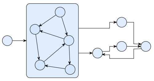
The option with identifier de.cau.cs.kieler.algorithm specifies which layout algorithm to use for a graph or subgraph. The value can be either the identifier of a layout algorithm or the identifier of a layout type. In the latter case the algorithm with highest priority of that type is applied. It is possible to set different values for this option on subgraphs of a hierarchical graph, where a subgraph is identified by a parent node. A layout algorithm is responsible to process only the direct content of a given parent node. An exception from this rule is made when the Layout Hierarchy option is active.
The following layout has been created by setting a force-based layout algorithm on the inner hierarchy level and a layer-based layout algorithm on the top level.
Available Algorithms and Libraries
- The KLay Project - Java implementations of standard layout approaches, augmented with special processing of graph features such as ports and labels.
- Randomizer - Distributes the nodes randomly; not very useful, but it can show how important a good layout is for understanding a graph.
Box Layout - Ignores edges, places all nodes in rows. Can be used to layout collections of unconnected boxes, such as Statechart regions.
- Fixed Layout - Does not compute a new layout, but leaves all nodes and edges where they are. If the Position and Bend Points options are set for the elements of the graph, the pre-defined layout is applied.
- OGDF (www.ogdf.net) - A self-contained C++ class library for the automatic layout of diagrams. The version that is shipped with KIELER is compiled as an executable that reads files in OGML format and outputs the computed concrete layout.
- Graphviz (www.graphviz.org) - An open source graph visualization tool with several graph layout programs, web and interactive graphical interfaces, auxiliary tools, libraries, and language bindings. Graphviz needs to be installed separately in order to be used within KIELER, since it is called in a separate process using the DOT language for communication.
Predefined Layout Types
- Layered - The layer-based method emphasizes the direction of edges by pointing as many edges as possible into the same direction. The nodes are arranged in layers and then reordered such that the number of edge crossings is minimized. Afterwards, concrete coordinates are computed for the nodes and edge bend points.
- Orthogonal - Orthogonal methods follow the "topology-shape-metrics" approach, which first applies a planarization technique, resulting in a planar representation of the graph, then compute an orthogonal shape, and finally determine concrete coordinates for nodes and edge bend points by applying a compaction method.
- Force - Layout algorithms that follow physical analogies by simulating a system of attractive and repulsive forces.
- Circular - Circular layout algorithms emphasize biconnected components of a graph by arranging them in circles. This is useful if a drawing is desired where such components are clearly grouped, or where cycles are shown as prominent properties of the graph.
- Tree - Specialized layout methods for trees, i.e. acyclic graphs. The regular structure of graphs that have no undirected cycles can be emphasized using an algorithm of this type.
Diagram Type
Diagram types are used to classify graphical diagrams for setting default layout option values for a set of similar diagrams. The diagram type of an element is specified with the layout option de.cau.cs.kieler.diagramType. Layout algorithms can declare which diagram types they support well, and give a priority value for each supported type. KIML decides at runtime which layout algorithm has the highest priority for a given diagram, so that the most suitable algorithm is always used. Usual values for such priorities are between 1 and 10, where the highest value should only be assigned if the algorithm is especially designed for diagrams of the respective type, or if it has proven to be very adequate for them. Lower values should be given if the algorithm is able to draw the diagrams correctly, but with lower quality of the resulting layout.
The following diagram types are predefined:
- General - This type is automatically assigned to all diagrams for which no specific type is declared. A layout algorithm that has the highest priority on the General diagram type is taken as the default algorithm when no further information on a diagram is available to KIML.
- State Machine - All kinds of state machines, automata, and activity diagrams. Examples: SyncCharts, UML Activity diagrams.
- Data Flow Diagram - Actor-oriented diagrams, where connections are mostly done between ports of nodes. These diagrams can only be handled properly by very special layout algorithms, such as those developed in the KLay project.
- Class Diagram - Class diagrams such as Ecore diagrams for the EMF or UML Class diagrams.
- Use Case Diagram - Use case diagrams as defined by the UML.
- Unconnected Boxes - Sets of nodes that have no connections and are treated as resizable boxes. This is related to mathematical packing problems. Example: Regions in SyncCharts.
Edge Routing
This option influences the way in which edges are routed between the nodes they connect. The following settings are available:
- POLYLINE
Edges consist of one or more segments defined by a list of bend points. - ORTHOGONAL
Edges are routed orthogonally, meaning that each segment of an edge runs either horizontally or vertically. - SPLINES
Edges are routed as splines (smooth curves). - UNDEFINED
No particular edge routing style is selected. Usually this value points to the default setting of the selected layout algorithm.
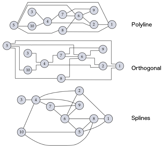
When used as layout option, the edge routing is set for a whole graph or subgraph, i.e. on a parent node. However, the property is additionally used for the output of the layout algorithm in order to mark individual edges. If the edge routing assigned to an edge is anything other than SPLINES, the bend points of that edge are interpreted with their normal meaning, i.e. straight lines are drawn between consecutive bend points. If, on the other hand, a layout algorithm marks an edge with the value SPLINES, the bend points have to be interpreted as control points for a series of cubic splines following this procedure:
- Start at the source point of the edge.
- As long as there are at least three bend points left:
- Draw a cubic spline segment to the third bend point with the other two bend points as control points.
- Use the third bend point as start point for the next segment.
- Consume the three bend points and proceed to the next segment.
- Check the number of remaining bend points:
- Two bend points – draw a cubic spline segment to the target point of the edge.
- One bend point – draw a quadratic spline segment to the target point of the edge.
- No bend point – draw a straight line to the target point of the edge.
Other Options
Additional Port Space
This option controls the usable space for ports on each side:
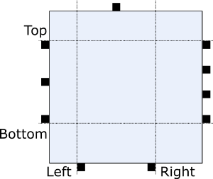
If the option is not set, the value of Port Spacing is used instead for all four components.
This option is only relevant if port constraints are FREE, FIXED_SIDE, or FIXED_ORDER. If size constraints include PORTS, the additional port space, together with the port spacing and the size of ports, determines a lower bound on the node size.
Alignment
Determines the alignment of a node in relation to other nodes of the same row or column. For layer-based algorithms, for instance, this option controls how a node is positioned inside its assigned layer.
Aspect Ratio
The aspect ratio of a drawing is the ratio of its total width to its total height. This option gives some control over that ratio, although in most cases it is only interpreted as a hint on how to arrange multiple connected components, hence the actual aspect ratio will probably be different from what has been specified with the option.
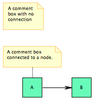
Comment Box
A node that is marked as comment box is treated as a label that needs to be placed somewhere. In contrast to normal node labels (modeled with a KLabel instance), comment boxes may have connections to other nodes, as in the following example.
Hypernode
A node that is marked as hypernode has a special role in the graph structure, since all its incident edges are treated as parts of the same hyperedge. Example: relation vertices in Ptolemy models.
Layout Hierarchy
If this option is supported and active, the layout algorithm is requested to process the full hierarchy contained in the input node. This means that instead of executing another algorithm on each hierarchy level, all levels are arranged in a single algorithm execution.
No Layout
Elements that are marked with this option are excluded from layout. This is used to identify diagram objects that should not be regarded as graph elements.
Port Alignment
The port alignment controls how ports are distributed over their respective edge.
This option is only relevant if port constraints are FREE, FIXED_SIDE, or FIXED_ORDER.
The following settings are possible:
UNDEFINED
Defaults toJUSTIFIED.JUSTIFIED
Distributes the ports evenly over the whole usable space (for usable space, see additional port space).BEGIN
Places the ports at top-/leftmost position with port spacing between them.CENTER
Places the ports centered in the usable space with port spacing between them.END
Places the ports at bottom-/rightmost position with port spacing between them.
Port alignment can also be set as specialized options portAlignment.{north|south|east|west}. These options overwrite the general policy for the respective side. Setting one of these to UNDEFINED defaults it to the general port alignment.
Port Anchor Offset
Since ports have a size, we need a concrete point inside the port that edges should start or end in. In KLay Layered, this is referred to as the port anchor. By default, the center of each port is used as its port anchor, but this behavior can be overridden by setting an explicit port anchor.
In the following example, the port anchor of the left port was moved upwards, while the port anchor of the second port was moved downwards:
Port Offset
The port offset is used to specify how much space a layout algorithm should leave between a port and the border of its node. This is usually zero, but doesn't have to be. If the offset is not defined for a given port, a layout algorithm can try to infer the offset from the port's coordinates and its node's size in the input graph. This of course requires both properties to be set to sensible values.
Set this property if one of the following cases applies:
- The port constraints on a node are set to FREE, FIXED_SIDES or FIXED_ORDER.
- The port constraints on a node are set to FIXED_RATIO or FIXED_POS, and the size of the node is not fixed. (Note that this is especially true for ports of compound nodes.)
Port Spacing
The port spacing determines how much space KLay Layered should leave between the ports of each side. This option is only relevant if the node size depends on the ports, that is, if the size constraints include SizeConstraint.PORTS.
Overview
Content Tools